Tried I2C LCD (liquid crystal display) with ESP32-WROOM-32
Contents
I2C LCD
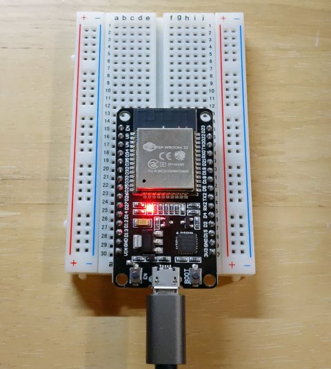
An article on running a sample program by connecting an I2C 1602 16×2 character LCD module display to an ESP32 (ESP32-WROOM-32) development module.

ESP32-WROOM-32 is a chip that adds Wi-Fi and Bluetooth to ESP32.
In this case, I used Aideepen brand products, but be aware that some modules have different pin assignments.
The pin layout of the product used in this project is the same as that of ESP32 DEVKIT V1, and a picture of it can be found here.

Features of LCD
There are a number of inexpensive LCD (Liquid Crystal Display) products available for 16 characters x 2 lines.
I chose a display with an I2C (Inter-Integrated Circuit) terminal for easy connection to the ESP32-WROOM-32.
The serial communication is not fast enough to display information such as temperature, humidity, and pressure.
LCD specifications are as follows
- Display size: 64.5mm x 16mm
- 5V DC (I was able to display at 3.3V, but the display is quite thin, see below for details)
- 16 characters x 2 lines
- Connection: I2C
I bought a product that has a module for I2C connection on the display.
It is also possible to purchase the display and I2C connection module separately.

Environment
The sample program was developed and compiled in the Arduino IDE on Windows, and written to the ESP32-WROOM-32 via USB.
The environment is as follows.
|
OS |
Windows 10 Home(64 Bit) |
|
Arduino IDE |
1.8.13 |
Wiring Diagram
Wiring diagram between ESP32-WROOM-32 module and I2C LCD.

- I measured VIN with a tester and it was 4.736V
- D21 of ESP32-WROOM-32 is connected to SDA and D22 to SCL
Advance preparation
Download the library for I2C connection
Install the library for I2C LCD in Arduino IDE.
When I tried to install the LiquidCrystal I2C library from this page, the last version was 1.1.2, but there was a 1.1.3 version by the same author, so I downloaded it.
(File name: LiquidCrystal_I2C-1.1.3.zip)
Include the library
Start the Arduino IDE and select Sketch > Include Library > Add .ZIP Library.

Select the ZIP file that you have just downloaded.

The library is added and the installation is finished.
By default, the library will be installed in a folder under C:\Users\Username\Documents\Arduino\libraries\.
To check the location, go to File > Preferences > Sketchbook Location.
If you want to uninstall the library, just delete this folder.

Sample program
The sample program is as follows.
It is just a sketch that counts up “Start” on the first line and a number on the second line.
I2cLcd-en.ino
/*
 *   I2C 1602 16x2 LCD test Sketch
 *
 */

#include <LiquidCrystal_I2C.h>

LiquidCrystal_I2C lcd(0x27,16,2);  // I2C addr、16x2

void setup() {
    Serial.begin(115200);
    lcd.init();
    lcd.backlight();
    /*
    lcd.autoscroll();
    */
    lcd.clear();
    lcd.setCursor(0, 0);
    lcd.print("Start");
    lcd.setCursor(0, 1);
    lcd.print("Count:");
}

void loop() {
    lcd.setCursor(6, 1);
    int times=millis() / 1000; // Number of milliseconds since program start
    lcd.print(times);
    /*
    lcd.scrollDisplayRight();
    */
    Serial1.println(times);
    delay(1000);
}
Additional explanation
For the commands available in LiquidCrystal Library, please refer to this page.
I2C address
First, the I2C address and the number of characters and lines of the character are specified.
LiquidCrystal_I2C lcd(0x27,16,2); // I2C addr, 16x2 characterThe default I2C address is 0x27 for the product I purchased, but other addresses may be assigned depending on the product.
The address is scanned with the address assigned by I2CScanner here.
I changed the first Serial.begin(9600); to Serial.begin(115200); and used it.
The I2C address can be changed with the solder jumper on the back.

In the above picture, A0, A1, and A2 are open (unconnected at the top and bottom), so the value is 0x27. However, if this jumper is shorted with solder, the address will change.
0: Short
1: Open
| A2 | A1 | A0 | I2C Address |
| 0 | 0 | 0 | 0x20 |
| 0 | 0 | 1 | 0x21 |
| 0 | 1 | 0 | 0x22 |
| 0 | 1 | 1 | 0x23 |
| 1 | 0 | 0 | 0x24 |
| 1 | 0 | 1 | 0x25 |
| 1 | 1 | 0 | 0x26 |
| 1 | 1 | 1 | 0x27 |
Display the number of seconds
millis() is a function that returns the time in milliseconds from when the Arduino board started executing the program to the present.
It divides the time by 1000, converts it to seconds, and displays it on the display with lcd.print.
    int times=millis() / 1000;
    lcd.print(times);
Auto-scroll
Although it is commented out in the sketch, it can be automatically scrolled from right to left.
lcd.autoscroll();Shifting one character
If you uncomment the text, it will scroll by shifting one character to the right.
lcd.scrollDisplayRight();Other Features
Contrast
The contrast (lightness and darkness) of the display can be adjusted with the semi-fixed resistors on the back.
When I first ran the sample program, nothing was displayed and I suspected a wiring or programming error, but after turning the variable resistor clockwise with a Phillips screwdriver, the display came back on.
However, when I turned the variable resistor clockwise with a Phillips screwdriver, the display came on. In the factory default state, even when connected to 5V, the characters were not visible unless the semi-fixed resistor was turned slightly clockwise.

When I connected VCC to 3.3V, I could barely see the variable resistors when I turned them clockwise to the maximum, so basically you should think you need a 5V power supply.
You can see the difference between the photo and the naked eye, but the 3.3V connection is with the variable resistor turned clockwise as far as it will go.

Backlight adjustment
There is a jumper pin on the back for backlight adjustment.
When it is removed, the backlight is turned off.
The intensity of the backlight can be adjusted by inserting a variable resistor (not tested).

This concludes this article.
I hope this article will be useful to someone somewhere.


Recent Comments