
M5Stack’s light sensor informs the Raspberry Pi when a rotary beacon light is on
Contents
M5Stack’s light sensor
I created a program that detects the lighting of the rotary beacon light with M5Stack’s light sensor and sends the lighting information via BLE (Bluetooth Low Energy).
On the Raspberry Pi side, it displays on the console which rotary beacon light has been turned on based on the received information.
Since BLE is a 4.2 standard, it has a communication speed of 1Mbps and can fly up to 100m in a place with good visibility.
Since the Wi-Fi of the Raspberry Pi is not used, this configuration can be used in places where LAN (wired or wireless) is not installed, thus expanding the range of use.

Overall configuration diagram
The overall configuration diagram is as follows.
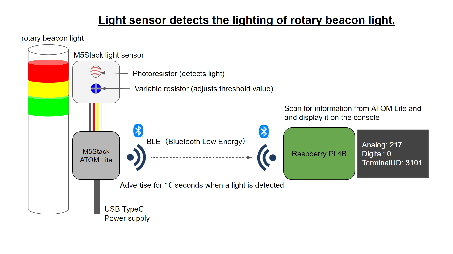
- Detect the lighting of the rotary beacon light with the photoresistor part of the light sensor for the M5Stack
- Receive the detection result (digital or analog) by M5Stack ATOM Lite
- Advertise (broadcast) the detection information via BLE (Bluetooth Low Energy) for 10 seconds
- Raspberry Pi 4B receives the BLE and displays it on the console
Prepared equipment, parts, and tools
Optical Sensor Unit for M5Stack
The photoresistor section detects light and outputs both digital and analog signals.
The digital value indicates whether the light is on (0) or off (1), and the threshold value can be adjusted with a variable resistor.
The analog value represents the intensity of the light as a number from 0 (light) to 4095 (dark).
It can also be connected to the M5Stack series via Grove compatible terminals.
光センサーの写真をここに載せる
M5Stack ATOM Lite
This time, I used M5Stack ATOM Lite to connect to the optical sensor unit.
The ATOM Lite is the smallest in size among the M5Stack series and the least expensive at the moment (May 2021).
Compared to the M5Stick-C, the ATOM Lite does not have a built-in battery, so it is necessary to secure a power supply (supplied via USB-Type-C).
- Size: 24 x 24mm
- Chip: ESP32-PICO-D4
- Wi-Fi, Bluetooth 4.2
- 4MB flash memory
- RGB LED
- Infrared LED
- Button x 2
- GPIO pins x 6
- Grove compatible interface
- Power input: 5V/500mA (USB Type-C)

Pins
On the back, there is a 5-pin connector on the left, a 4-pin connector on the right, and a Grove compatible connector in the center.
Left side
From the top.
- 3V3: Out
- G22: In/Out
- G19: In/Out
- G23: In/Out
- G33: In/Out(Analog)
right side
From the top.
- G21: In/Out
- G25: In/Out
- 5V: Out
- GND
Grove compatible terminals
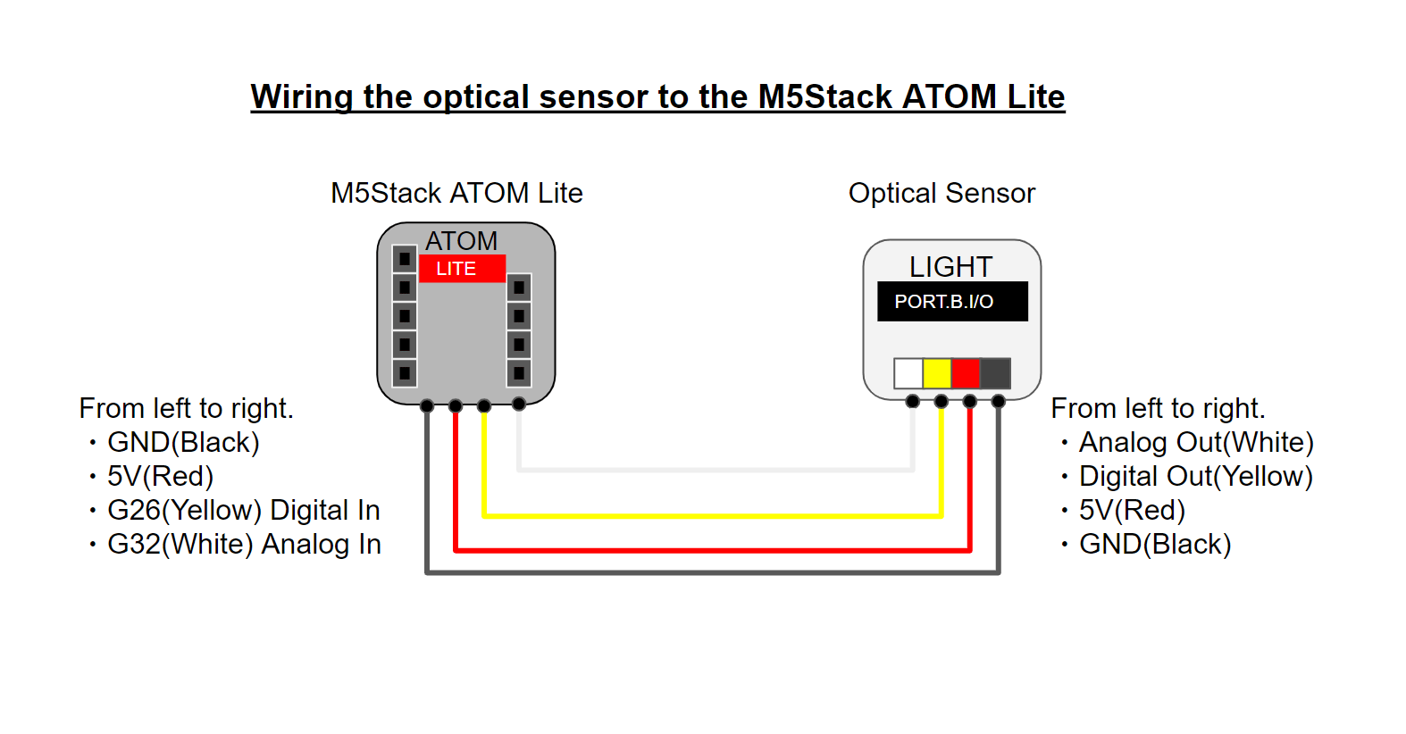
From left to right.
- GND
- 5V: Out
- G26: In/Out
- G32: In/Out(Analog)
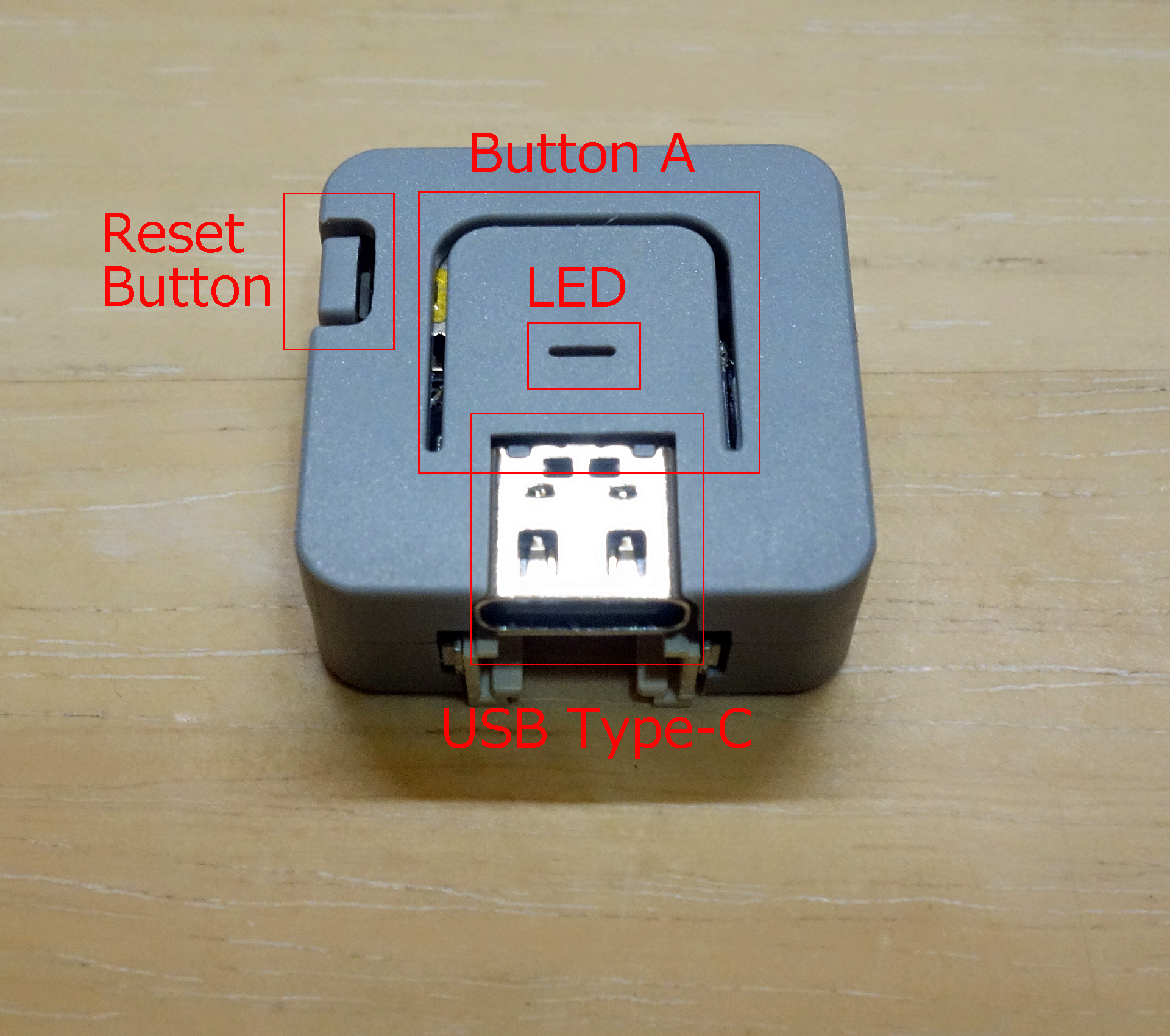
front side
On the front, there is a USB Type-C connector for power supply, button A and LED in the center, and a reset button on the left.
This time I connected it to ATOM Lite, but it can also be connected to other M5Stack series and M5Stick-C.
I also connected it to my M5Stick-C, and it worked fine.
Raspberry Pi 4B
In order to receive the BLE signal from ATOM Lite and display the information on the console, I prepared a Raspberry Pi 4B.
The Raspberry Pi 4B supports Bluetooth Ver. 5.0 (125 kbps and a distance of up to 400 m), but since the Bluetooth version on the ATOM Lite side is 4.2, communication is based on 4.2.

Wiring Diagram
The wiring diagram is shown below.
Program
The development environment for ATOM Lite, which acquires the values of the light sensor and advertises them via BLE, was created in C++ with the Arduino IDE installed on Windows 10.
On the other hand, the Raspberry Pi, which receives the data and displays it on the console, was created in Python.
ATOM Lite
Building the Environment
For details on downloading and installing the Arduino IDE, please refer to the previous article.
- Arduino IDE Download
- Installation
- Installing Additional Software
- Adding a board manager
- The following steps are done.
Installing the library
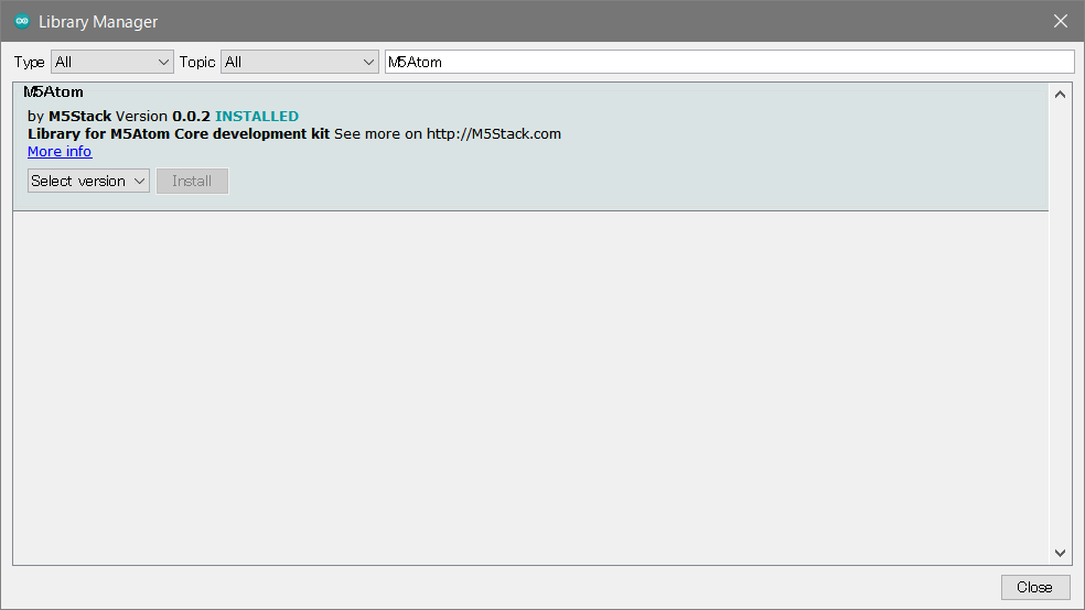
Install the library for the M5Atom we will be using.
From the Arduino IDE menu, go to Sketch -> Include Library -> Manage Libraries, search for “M5Atom” in the search field, and install the library that appears.
I installed 0.0.2, which is the latest version at the moment (May 2021).
Tool Settings
The settings for the tools in the Arduino IDE menu are as follows
- Board: ESP32 Arduino -> Select M5Stack-ATOM (see below for details)
- Upload Speed: 1500000 (reduce the speed such that a communication error occurs)
- Partition Schema: Initial value
- Core Debug Level: None
- Serial port: COMn (n is a number, see below for details)
- Specify the following.

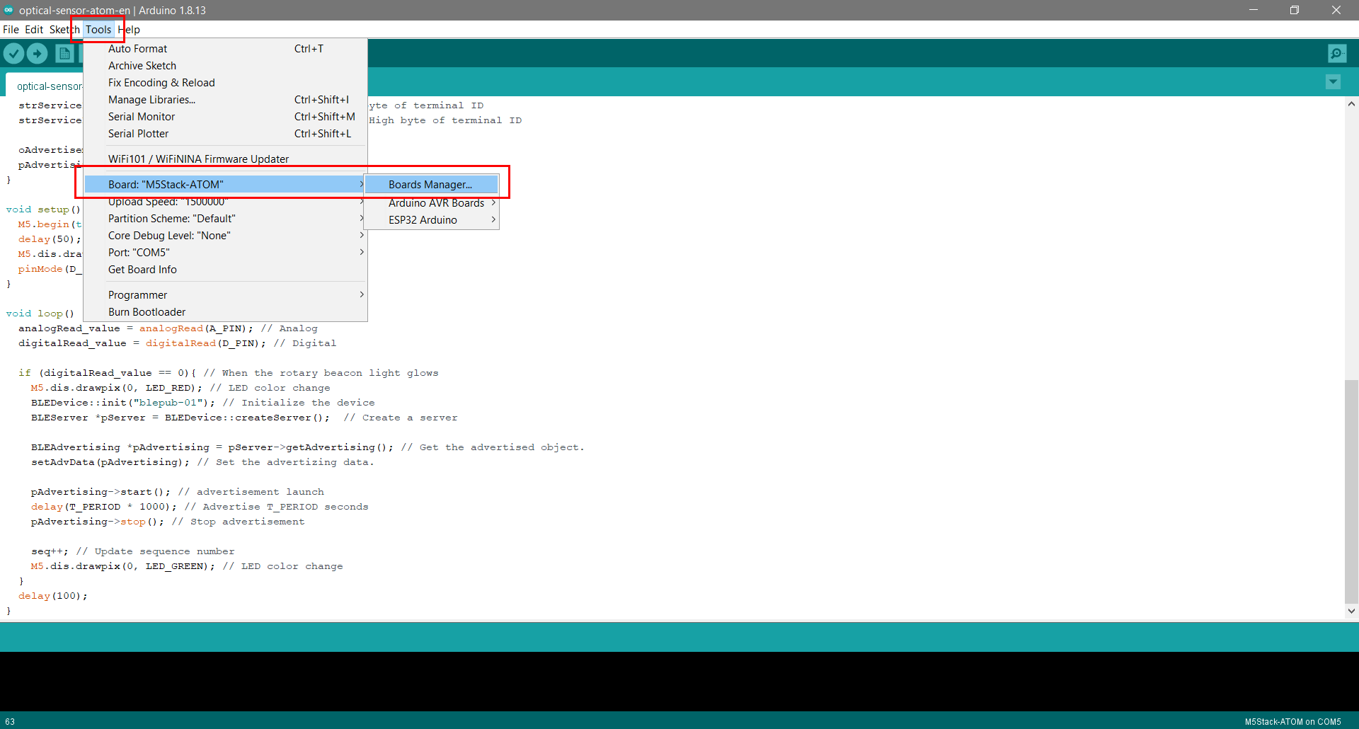
Board management
In the Arduino IDE menu, go to Tools -> Board -> ESP32 Arduino to see the list.
If you don’t see M5Stack-ATOM in the list, update the esp32 from the Boards Manager.
Select Tools -> Board -> Boards Manager.
Selecting “Updateable” for the type will narrow down the list to only those boards that can be updated.
The esp32 version 1.0.4 did not show M5Stack-ATOM in the list, so I changed the “Select Version” field to the latest (as of May 2021) 1.0.6 and clicked the “Update” button.

After updating the board esp32 version to 1.0.6, the list now shows M5Stack-Core2 and others in addition to M5Stack-ATOM.

Checking the COM port
Connect the PC (Type-A) and ATOM Lite (Type-C) with a USB cable.
A COM port will be assigned automatically, so specify it from the Arduino IDE menu.
If you have only one device connected to the serial port, select Tools -> Serial Port from the Arduino IDE menu, and only one COM port will be displayed.
When multiple COM ports are displayed, check the COM port (in Windows 10) as follows
Right-click on the Windows Start menu and select Device Manager.
The Device Manager will appear, and while displaying the ports (COM and LPT), plug and unplug the USB cable to find out that the newly added COM port is the ATOM Lite COM port.

Source Code
optical-sensor-atom-en.ino
/**
 *  Created on 2021-04-27
 *
 *  Light sensor unit detects the lighting of rotary beacon light.
 *  When detected, the LED changes to red and then advertises for a certain number of seconds.
 *
 *  @author: Souichirou Kukuchi
 */
#include "M5Atom.h"
#include <BLEDevice.h> // Bluetooth Low Energy
#include <BLEServer.h> // Bluetooth Low Energy
#include <BLEUtils.h> // Bluetooth Low Energy

#define T_ID 3101 //  terminal ID
#define T_PERIOD 10 // Number of seconds to send advertizing packets
#define A_PIN 32 // Analog Pin number
#define D_PIN 26 // digital Pin nunber
#define LED_GREEN 0xf00000
#define LED_RED 0x00f000
#define LED_BLUE 0x0000f0
#define LED_WHITE 0x707070

RTC_DATA_ATTR static uint8_t seq;

uint16_t analogRead_value = 0; // Small: bright, Large: dark 0~4095
uint16_t digitalRead_value = 0; // 0: bright. 1: dark
uint16_t terminalid = T_ID; // Terminal ID

void setAdvData(BLEAdvertising *pAdvertising) { // Formatting Advertising Packets
  BLEAdvertisementData oAdvertisementData = BLEAdvertisementData();
  oAdvertisementData.setFlags(0x06); // BR_EDR_NOT_SUPPORTED | General Discoverable Mode

  std::string strServiceData = "";
  strServiceData += (char)0x0a; // Length(10Byte)
  strServiceData += (char)0xff; // AD Type 0xFF: Manufacturer specific data
  strServiceData += (char)0xff; // Test manufacture ID low byte
  strServiceData += (char)0xff; // Test manufacture ID high byte
  strServiceData += (char)seq; // sequence
  strServiceData += (char)(analogRead_value & 0xff); // Lower byte of analog
  strServiceData += (char)((analogRead_value >> 8) & 0xff); // High byte of analog
  strServiceData += (char)(digitalRead_value & 0xff);  // Lower byte of digital
  strServiceData += (char)((digitalRead_value >> 8) & 0xff); // High byte of digital
  strServiceData += (char)(terminalid & 0xff); // Lower byte of terminal ID
  strServiceData += (char)((terminalid >> 8) & 0xff); // High byte of terminal ID

  oAdvertisementData.addData(strServiceData);
  pAdvertising->setAdvertisementData(oAdvertisementData);
}

void setup() {
  M5.begin(true, false, true); // initialize UART, I2C, LED
  delay(50);
  M5.dis.drawpix(0, LED_GREEN); // LED color change
  pinMode(D_PIN, INPUT_PULLUP); // Set to digital input
}

void loop() {
  analogRead_value = analogRead(A_PIN); // Analog
  digitalRead_value = digitalRead(D_PIN); // Digital

  if (digitalRead_value == 0){ // When the rotary beacon light glows
    M5.dis.drawpix(0, LED_RED); // LED color change
    BLEDevice::init("blepub-01"); // Initialize the device
    BLEServer *pServer = BLEDevice::createServer();  // Create a server

    BLEAdvertising *pAdvertising = pServer->getAdvertising(); // Get the advertised object.
    setAdvData(pAdvertising); // Set the advertizing data.

    pAdvertising->start(); // advertisement launch
    delay(T_PERIOD * 1000); // Advertise T_PERIOD seconds
    pAdvertising->stop(); // Stop advertisement

    seq++; // Update sequence number
    M5.dis.drawpix(0, LED_GREEN); // LED color change
  }
  delay(100);
}
Supplementary explanation
Please refer to the comments in the source code for details, and I would like to make a few additions.
The lighting of the rotary beacon light is judged by the digital value (digitalRead_value) of the light sensor, but it can also be judged by the analog value (analogRead_value).
In this case, I used the digital value and adjusted it with the variable resistance of the light sensor itself.
Also, the data for advertising is assembled with setAdvData in line 29.
For details on the data layout, please refer to the setAdvData chapter of the previous article.
The company ID is 0xff * 2 for testing.
The upper limit of the message size is 31Byte, so it is not possible to send such a large size of data.
The items that are being advertised are
- Analog value
- Digital value
- Terminal ID (unique value for each optical sensor)
The following three items are being sent.
Writing the program
Select Sketch -> Upload from the Arduino IDE menu, or press Ctrl+U to compile and write the program (sketch) executable to the ATOM Lite.
If the writing is successful, the message “Done uploading” will be displayed.

Raspberry Pi
The program structure of the Raspberry Pi on the side receiving the data is as follows.
Directory structure
The following directory structure is used.
├─$HOME/.local/
│  │
│  ├─optical-sensor
│  │  │  optical_sensor_catch.py
│  │  │
│  │  ├──log
│  │  │  error.log
│  │  │
The programs were saved in a directory under $HOME/.local/
error.log is a file that stores the error log when an exception occurs for some reason.
Source Code
optical_sensor_catch_en.py
# -*- coding: utf-8 -*-
"""
Created on Wed Apr 28 16:20:42 2021

・Display the value of the data sent by BLE from M5Stack ATOM Lite.

@author: Souichirou Kikuchi
"""

from bluepy.btle import DefaultDelegate, Scanner, BTLEException
import sys
import struct
import os
import csv
from datetime import datetime as dt

class ScanDelegate(DefaultDelegate):
    def __init__(self): # constructor
        try:
            DefaultDelegate.__init__(self)
            self.lastseq = None
            self.lasttime = dt.fromtimestamp(0)
        except:
            ex, ms, tb = sys.exc_info()
            self.put_error_log(type(ms))

    def handleDiscovery(self, dev, isNewDev, isNewData):
        try:
            if isNewDev or isNewData: # New device or new data
                for (adtype, desc, value) in dev.getScanData(): # Repeat for as many data as you need.
                    if desc == 'Manufacturer' and value[0:4] == 'ffff': # companyID for testing
                        delta = dt.now() - self.lasttime
                        # Only use the first one retrieved.
                        if value[4:6] != self.lastseq and delta.total_seconds() > 11:
                            self.lastseq = value[4:6] # Save Seq and time
                            self.lasttime = dt.now()
                            (analog, digital, terminal_id) = struct.unpack('<hhh', bytes.fromhex(value[6:])) # h is a 2Byte integer (take out 3)
                            print('Analog: {0}, Digital: {1}, Terminal ID: {2} '.format( analog, digital, terminal_id))
        except:
            ex, ms, tb = sys.exc_info()
            self.put_error_log(type(ms))

    def put_error_log(self, message): # Output the error log file.
        ERR_LOG_FILE = './log/error.log'
        if (os.path.isfile(ERR_LOG_FILE)): # When the file exists
            f = open(ERR_LOG_FILE, 'a') # Loading in append mode
        else: # If there is no file, create a header.
            f = open(ERR_LOG_FILE, 'w') # Read in write mode
        writer = csv.writer(f)
        writer.writerow(['{0:%Y-%m-%d %H:%M:%S.%f}'.format(dt.now()), message])
        f.close()

if __name__ == "__main__":
    scanner = Scanner().withDelegate(ScanDelegate())
    try:
        print('Optical Sensor Catch Start') # Program start
        while True:
            scanner.scan(5.0) # Scan. Let ScanDelegate take care of the rest after finding the device.
    except BTLEException:
        ex, ms, tb = sys.exc_info()
        print('BLE exception '+str(type(ms)) + ' at ' + sys._getframe().f_code.co_name)
        pass
    finally:
        print('Optical Sensor Catch End')
Supplementary explanation
Please refer to the comments in the program for details.
When a BLE signal is found by repeated scanning, the handleDiscovery method of the ScanDelegate class is executed.
In the handleDiscovery method, in addition to checking the company ID, only the first data received is targeted since it will be advertised continuously for 10 seconds.
Execution
Since the program accesses the BLE module, it needs to be run with sudo and with administrative privileges.
cd ~/.local/optical-sensor
sudo python optical_sensor_catch_en.py
The execution result is as follows.
When you shine light on the light sensor, the value of the light sensor is displayed on the console of the Raspberry Pi.

At the end.

The position of the rotary beacon light and the light sensor needs to be adjusted at the factory with a variable resistor.
The line at the factory is about 20 meters long, but the signal was received even with BLE4.2 (Bluetooth Low Energy).
Also, the Raspberry Pi program in this article only displays information on the console.
In reality, we are building a system that uses the information received from each sensor to inform the user of error conditions using voice.
This concludes this article.
I hope this article will be useful to someone somewhere.


Recent Comments